Mespelare proof-of-concept
 Before putting the Mespelare board into production, I wanted to do a final proof-of-concept test to make sure the hardware design is 100% correct before ordering the boards and components. I wanted my first professional production PCBs to come out 100% perfect, I would hate it to have to bodge up 30 boards…
Hardware
Changes
To fix the mistakes I learned from testing the Mespelare v6 board, I made another prototype, Mespelare v9.
This design incorporates the following changes:
- Changed pin assignments, mostly because I used pin RA4 in v6, which isn’t available on the 18F45K80. Another lesson in reading the datasheet.
- Added a capacitor to pin 23 as per the datasheet.
- Changed the drill hole diameter to 2,2mm.
- Added a second 12V power regulator so I can increase the bus voltage to 24V DC to minimize voltage drop effects.
- Corrected the footprint for L2, in v6 it was too small.
- Changed the footprint for the solder bridges under the ULN2003’s, so that they can be easily bridge by a drop of solder if the board is not populated by a ULN driver.
- Added ‘flyback’ diodes for both LDO’s to protect against short-circuit of the power bus, as per the datasheet.
- Added VSCP logo to the PCB design.
- Added a larger pad for the TX pin so that a wire can be soldered on for debugging purposes.
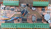
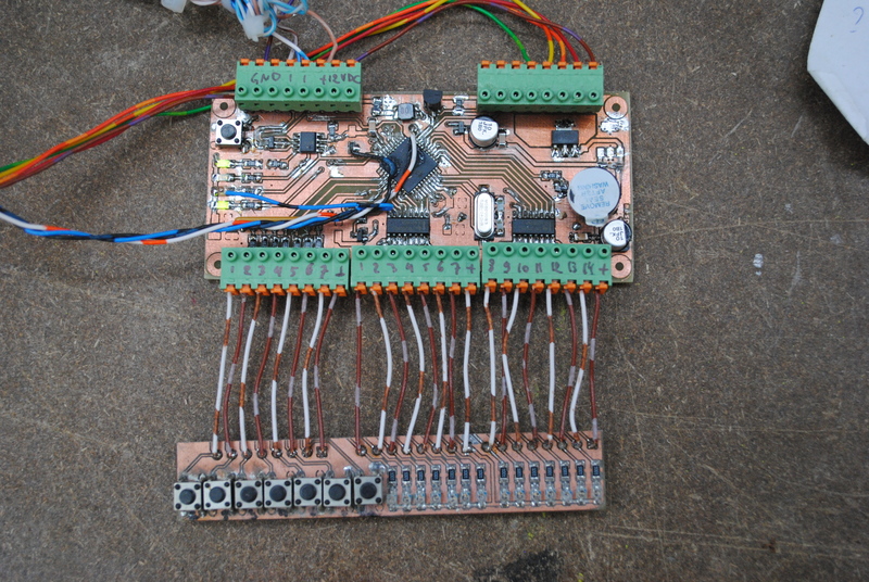
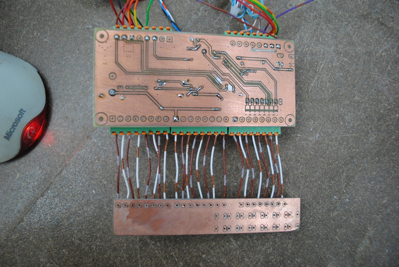
The PCB design was printed on a transparent laser sheet, transferred to a pre-sensitized PCB using a UV face tanner, developed in drain cleaner (NaOH) and subsequently etched. I populated the board by hand.
Testing
The hardware was tested using the test files made for the v6 board. Obviously a new pin_defines.h file was used to reflect the hardware changes.
Firmware
The firmware needed to be adapted for the changes made in the hardware (mostly changing pin assignments). It was then tested for correct functionality:
- short circuits between power rails and ground
- bus power has correct voltage
- correct voltages on power rails
- oscillator runs
- bus communication works
- button inputs and outputs work (using a button and LED test jig)
- VSCPworks can read and write the module
- DM works as expected
Resources
- Schematic & PCB (Eagle CAD)
- Firmware (MPLAB X & C18)
- Mespelare GitHub repository